Project 006
Femoral Fracture Fixation Plate
Designed and prototyped an internal fixation plate for a fractured femur, combining back-of-envelope stress analysis with iterative CAD prototyping to meet a target factor of safety against bending failure.
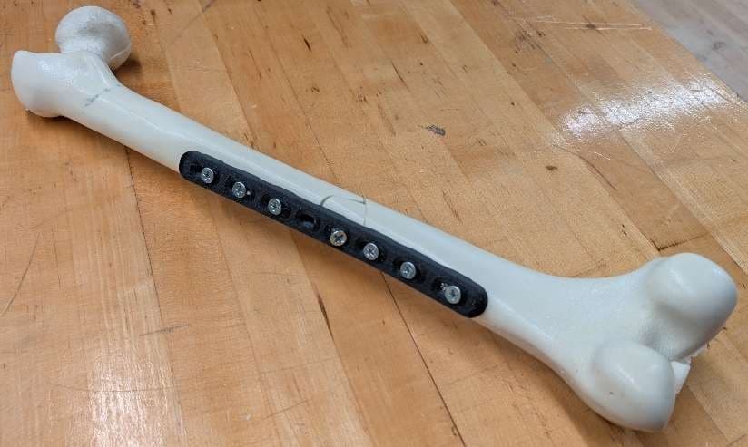
Final Prototype, Installed
Overview
This project focused on designing a bone plate to internally fix a fractured femur, an implant that needs to be stiff enough to bear a patient's full body weight while still allowing the bone itself to heal properly.
The design process combined hand calculations for bending stress with several rounds of CAD prototyping and physical testing on a model femur.
Back-of-Envelope Calculations
Loading Scenario
A worst-case subject weight of 200 lb was assumed, with load distributed evenly between the legs and, at the fracture site, evenly between the femur and the plate itself. This set the design load at 25 lb per side, which produced an internal bending moment of 64.7 lb·in at the center of the plate, the region most prone to bending failure.
Stress & Factor of Safety
The area moment of inertia of the plate's cross section, accounting for the screw hole cutout, was used to compute the maximum bending stress at that section. That stress was compared against the yield strength of 316L stainless steel (about 29.7 ksi) to solve for a factor of safety.
Targeting a factor of safety of 2, these equations were solved for plate width and thickness, converging on w = 0.7 in and t = 0.226 in, both within the project's dimensional constraints.
Prototyping
Gen 1
The first prototype incorporated slots along its length to allow flexibility in screw placement and axial compression, but was flat on the underside with no contour to the bone, and its single center slot made it difficult to secure a screw at the fracture site itself.
Gen 2
The second prototype added a curved profile with raised ridges on the underside to minimize direct contact with the bone and reduce stress shielding, along with angled center holes to properly seat a lag screw across the fracture line.
Design Validation
| Constraint | Target | Result | Status |
|---|---|---|---|
| Factor of Safety | FOS ≥ 2 against bending | FOS = 2 at w = 0.7 in, t = 0.226 in | Pass |
| Bone Contact | Minimize plate-to-bone contact | Curved ridges lift plate off bone | Pass |
| Fracture Fixation | Secure lag screw at fracture site | Angled center holes seat screw | Pass |
| Dimensional Limits | Within project size constraints | w = 0.7 in, t = 0.226 in | Pass |
Path Forward
The Gen 2 design met the project's constraints and improved on Gen 1 in every category, but there's still room to refine the underside curvature to better match real bone geometry, trim unnecessary material, and address screws that protrude slightly when driven in at an angle, likely by adjusting the countersink geometry of the center holes.
Team
Group 30
Timothy Augusteijn • Caleb Beswick • Maddox Caldwell • Nicholas Campbell